While the axle is torn down, it might be a good idea to perform some other upgrades. There are a few aftermarket covers that are much stronger than the factory cover and unlike it, come with a drain plug. If only regearing, installing a traction aiding device may be a good idea and vice versa. This could also be a good opportunity to install a diff lube temperature sensor.
The factory service manual recommends 75W-90 dino lube for the rear diff. 75W-140 is a good replacement for heavy duty off-roading and recommended by the factory service manual as a tow lube for the rear diff. After the Mopar lube is drained in 500 miles, it will be replaced with AMSOIL Severe Gear. If you're (re)installing a limited slip and not a locker, Limited Slip Additive must be added to the rear diff lube.
In addition to the above specialized tools, a comprehensive collection of common metric and standard mechanics tools is also required. This includes, in frequency of usage, 1/2 and 3/8 drive ratchets and sockets, wrenches, hammers, Dremel and grinding bits, drill and steel bits, vice-grips, punches, and screw drivers. While there is also no way to complete this project without exacting delicacy, there is also no way to complete it project without brute force.
| Jacking the Liberty |
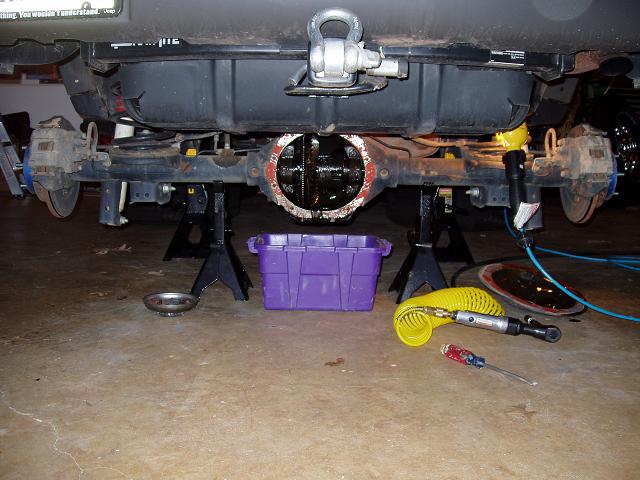
| The objective here is to raise the unibody and drop the rear axle as much as possible to allow access to the entire differential cover. First and fore most, place some chocks in front and behind each front wheel. The parking brake can't be applied because it will interfere with removing the axle shafts. When the front has been secured, jack up the unibody and place one larger jack stand just in front of each low control arm mount. On one side, remove the wheel and let the axle down as far as possible onto a smaller jack stand. Repeat on the other side. |
 |
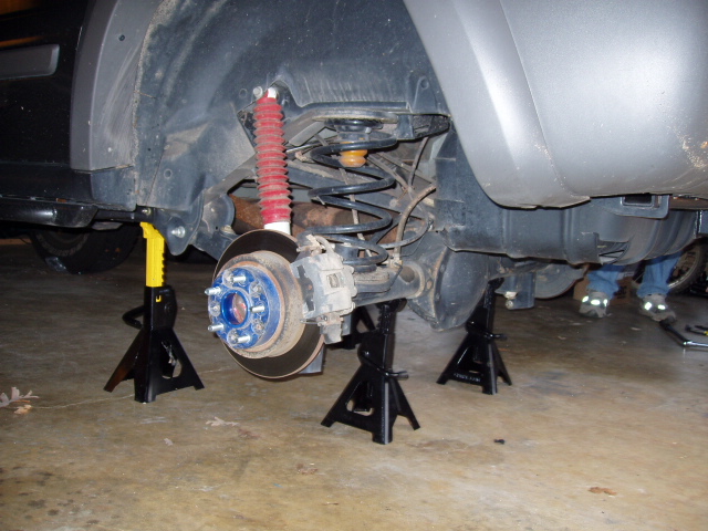 |
| Fig 1: Body jacked up |
Fig 2: Axle dropped |
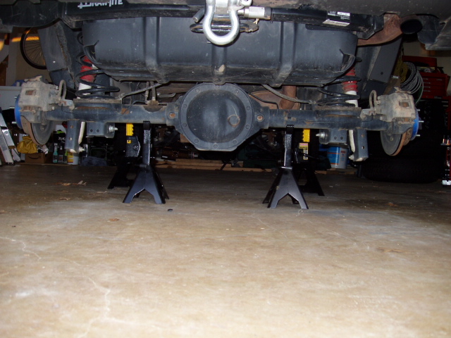 |
On the left you can see the desired end result. There now should be plenty of room to remove the diff cover and perform the install. If more room is needed, it is always possible to completely remove the axle by disconnecting a few bolts and brake lines. Note the blue wheel spacers in the pictures. These are SpiderTrax WHS-002 wheel spacers and won't be present on stock Libertys. |
| Fig 3: Body jacked up and axle dropped with diff cover completely visible |
|
| |
| Disconnecting the driveshaft |
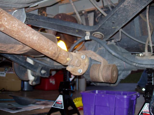
| The driveshaft needs to be removed from the pinion yoke. Before disconnecting the driveshaft, place a mark between it and the pinion yoke so they can be reconnected in their original orientation. Liquid Wrench and an impact wrench will go a long way when removing the four rusted bolts. If you don't have an impact wrench, a long breaker bar should do the job. While a large torque wrench might seam like a good alternative, breaking bolts is hard on it and will ruin its calibration. Putting the transmission in Park will stop the driveshaft from spinning while loosening the bolts. For easier access to the upper bolts you can put the transmission in Neutral, spin the driveshaft, return it to Park, and remove the now more accessible bolts. A lip stops the driveshaft from falling off when the bolts are removed. The shaft first needs to be pushed towards the front of the Jeep to clear the lip and then slid over to the side to get it out of the way. |
 |
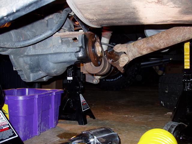 |
| Fig 4: Driveshaft connected |
Fig 5: Driveshaft disconnected |
| |
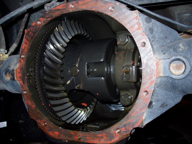
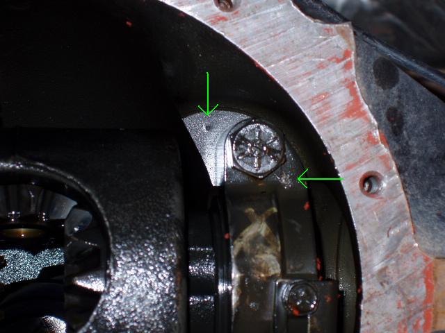
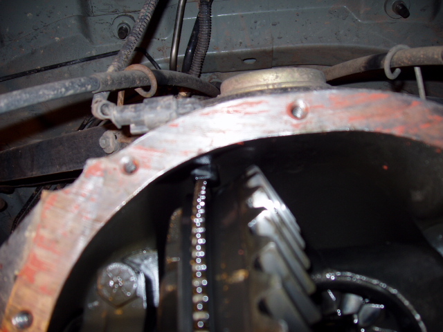
| Removing the diff cover |
| It's a good idea to clean the housing before breaking any seals. Once clean, place a good sized bucket under the diff, remove all 10 diff cover bolts and fill plug, and gently pry the bottom of the diff cover away from the housing. When most of the gear lube has drained into the bucket, completely remove the cover and use a scraper to clean the RTV gasket off of the housing. The images below show the housing with the factory limited slip differential installed. |
 |
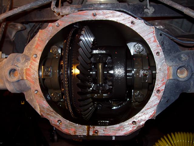 |
| Fig 6: After draining the gear lube |
Fig 7: Inside of the housing with most of the RTV gasket removed |
| |
| Removing the axle shafts |
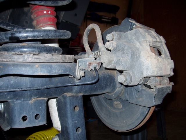 |
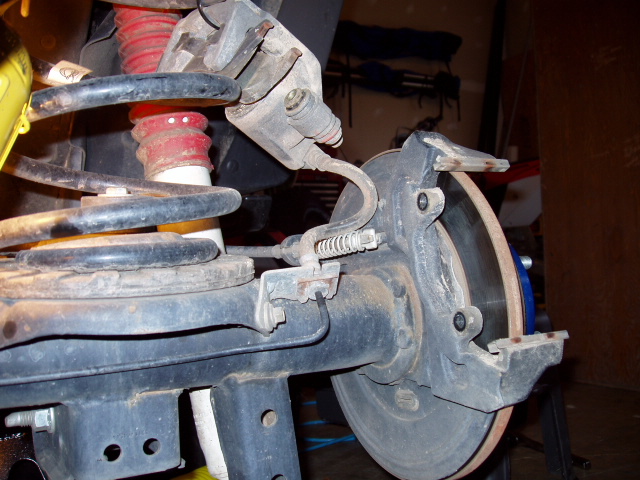
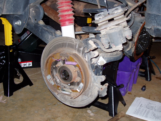
Remove the brake calipers by squeezing the latch at the bottom of the calipers while simulataneously pulling the bottom back towards the rear of the Jeep. Once the buttom has been released the top will just drop out. To keep stress off the brake lines, use tie wraps to suspend the calipers from the rear springs. |
| Fig 8: Brake caliper and mounting bolts |
|
 |
 |
| Fig 9: Back of brake rotor with caliper removed |
Fig 10: Front of brake rotor with caliper suspended from rear spring |
| Spin one of the axle shafts or the pinion yoke so that the center shaft lock bolt is facing towards the back of the Jeep. Remove the bolt and tap the center shaft half-way out with a hammer and punch. Spin one of the axle shafts 180 degrees to reveal the now protruding center shaft and pull it the rest of the way out. With the center shaft removed, push each axle shaft inwards until it stops. This will reveal the c-clips as shown in the lower right picture. The c-clips should slide off of the axle shafts quite easily. If they don't, you need to push the axle shafts in further. When the c-clips are removed, pull each axle shaft out. While removing the two shafts, the entire weight needs to be supported in order to protect the seals. With the axle shaft removed, the emergency drum brakes and axle shaft bearings are visible as shown in the far lower left picture below. |
 |
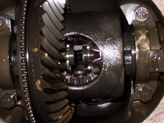 |
| Fig 11: Carrier with center shaft lock bolt (head pointing right in carrier concave) |
Fig 12: Carrier with c-clips revealed |
 |
 |
| Fig 13: Axle tube with axle shafts abscent |
Fig 14: Removed axle shafts |
| |
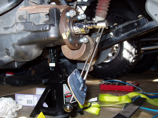
| Making a Preliminary Backlash Check |
 |
Now is a good time to check the factory backlash measurement. Magnetically couple the indicator base to the diff housing and adjust the arms so the indicator needle makes contact with the top heal of the outer-most ring gear tooth. In your setup the needle should be more perpendicular to the tooth. The image to the left shows needle leaning slightly to the left; this was corrected to be perfectly perpendicular before the measurments were taken. Be sure to put enough pressure on the needle to move the dial abot 1/2". On the other side of the diff housing, clamp the pinion yoke to the housing to immobilize the pinion gear. Now grab the carrier and rotate it as far as possible in one direction and then the other. Subtract these two dial measurements to get the backlash. To ensure consistancy, take the measurement here as well as 90 degrees further around the ring gear. The true perfectionist can take four measurements of equal spacing around the gear. While the factory service manual recommends a maximum backlash of .008", this differential's backlash was .012". |
| Fig 15: Checking the backlash with a dial indicator (adjuster locks removed) |
|
| |
| Removing the carrier |
| Mark each carrier bearing cap and adjacent housing location with unique matching marks. These marks will allow the carrier bearings to be reinstalled in the correct orientation to match the existing wear patterns. |
 |
 |
| Fig 16: Left carrier bearing double cap marks |
Fig 17: Right carrier bearing single cap marks |
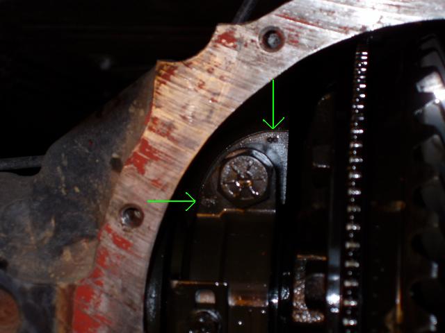
| Unplug and unbolt the ABS sensor and pull it out of the diff housing. The sensor does not mechanically engage the carrier. Remove the carrier bearing preload adjuster locking tab from the right side. On the left side, just loosen the tab as it is impossible to remove it with the carrier installed. Loosen the carrier bearing caps but don't completely remove them. If the caps are completely removed, the carrier will fall onto the floor when the carrier bearing preload adjusters are loosened. Insert the Chrysler bearing preload tool into the right axle tube and loosen the right carrier bearing preload adjuster. The left carrier bearing preload adjuster can't be loosed because the locking tab can't be removed yet. With the carrier bearing caps and preload adjuster loosened, the carrier should now be sitting loosely in the housing. Hold the rather heavy carrier so it doesn't fall onto the floor and finish removing the carrier bearing caps. Place all the components somewhere free of dirt and debris and clean them. |
 |
 |
| Fig 18: ABS sensor |
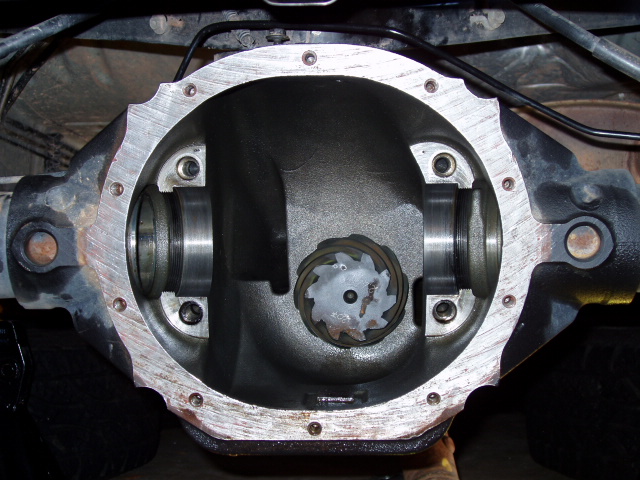
Fig 19: Housing sans carrier, carrier bearing caps and adjusters, and ABS sensor |
| |
| Removing the pinion gear |
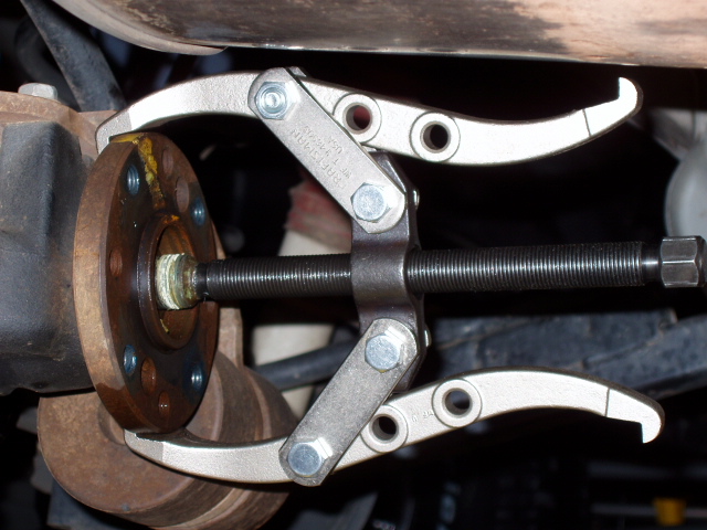
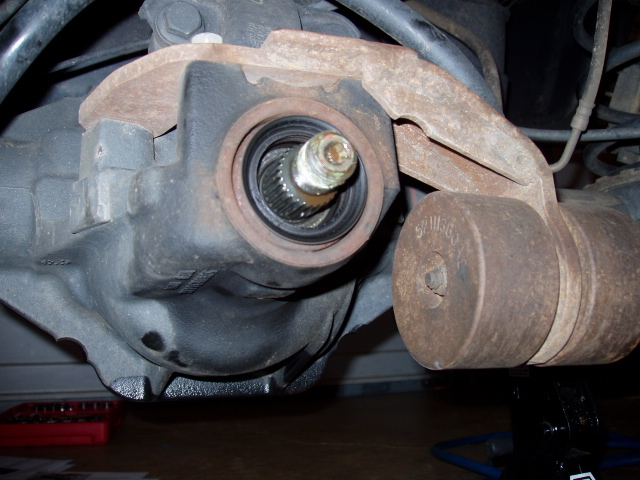
| Remove the pinion nut with a impact wrench or breaker bar while a friend clamps the pinion flange with a pair of vice grips. Again, Liquid Wrench really does help here. Setup a puller as in Fig 20 and slowly pull the flange off of the pinion shaft. It should come off fairly easily. When the flange has been removed, use a 3 pound dead blow hammer to drive the pinion out of the housing. To catch it when it flies out, place a box filled with crumpled newspaper on the opposite side of the housing. In the writing of this guide, the pinion was frozen to the housing and its removal required the use of a rather large sledge hammer. |
 |
 |
| Fig 20: Pinion flange with puller installed |
Fig 21: Pinion shaft with flange removed and seal visible. |
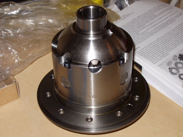
| Installing the Tone Ring |
| The Jeep Liberty uses a tone ring on the 8.25" carrier for ABS and speedometer functions. The tone ring is sandwiched between the carrier and the ring gear. Remove the left hand threaded ring gear bolts and ring gear from the old carrier. The service manual removal procedure involves knocking the edge of the ring gear with a dead blow hammer until it comes loose. A blow to a punch placed in each ring gear bolt hole seemed more effective. With the ring gear removed, knock the tone ring from the old Chrysler carrier and then gently knock it onto the new ARB carrier. Be sure to maintain its orientation relative to the carrier and thoroughly clean both the tone ring and the new carrier. |
 |
 |
| Fig 21: Brand new cleaned ARB Air Locker |
Fig 22: Locker with tone ring installed |
| |
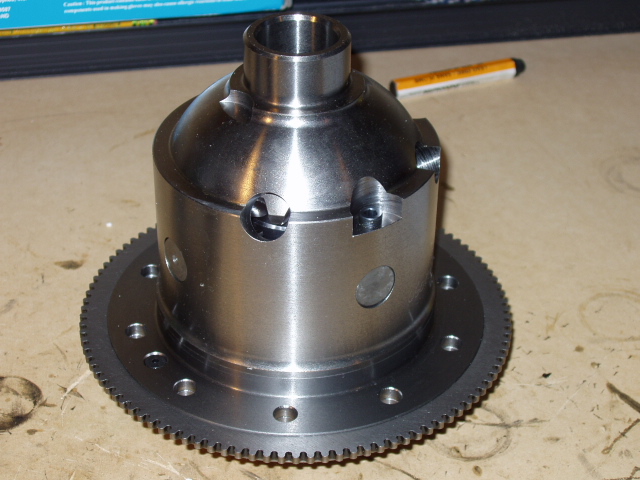
| Installing the Ring Gear |
 |
Thoroughly clean the exterior of the ring gear, remove any oil and debris from the bolt holes, and heat in an oven to 200 degrees farenheit. To facilitate ring gear installation, the locker comes with grease already applied to shoulder. Line up the bolt holes as accurately as possible and slip the gear onto the locker. The gear should have expanded enough to be slid all the way down to the locker's flange without the use of a hammer.With the gear butting the flange, flip the locker over and finger tighten all of the left hand threaded ring gears bolts. By the time the bolts are installed, the ring gear should have contracted back to its original size and frozen into the correct position. In a criss-cross pattern, remove each ring gear bolt, apply Loctite, and reinstall with a torque of 75 ft/lbs. If the airline is obscuring the bolts, spin the airline bearing rather than bend and weaken the airline. |
| Fig 23: Locker with tone ring and ring gear installed |
|
| |
|
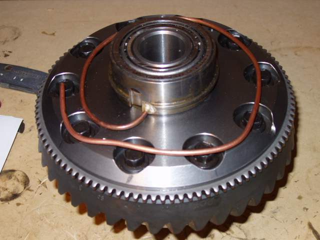
| Installing the Carrier Bearing |
 |
Thoroughly clean the inside diameter of the bearing cone and heat the cone in an oven to 200 degrees farenheit. To facilitate cone installation, apply high pressure grease to the bearing shoulder on the locker. Slip the cone onto the locker as far as hand power will allow. While writing this guide, the cone didn't expand enough to slide all the way down the locker's shoulder without the use of a hammer. Place the outside of the previously removed pinion flange on top of the cone. Pound it with a dead blow hammer to drive the bearing all the way down the shoulder. Be sure not to damage the airline while handling the locker. Now is a good time to put the new pinion bearing races into the freezer so they'll be contracted when it time to install them. |
| Fig 24: Locker with carrier bearing installed on left. Pinion flange on right. |
|
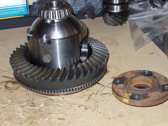
| Making Setup Bearings |
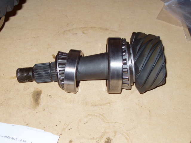 |
The pinion depth shims are installed on the pinion between the gear head and the inner pinion bearing. The pinion bearings are a very tight fit and will become damaged if removed and replaced multiple times. To allow easy pinion removal from the housing and easy shim modification, it's a good idea to make a set of setup bearings. These are the same as the existing bearings, only with the inside diameter honed out just enough so they can slip easily on and off of the pinion shaft. A Dremel will make a few minutes work of the job. The old outer pinion bearing will just fall off when the old pinion is removed from the housing; it can be reused to create the outer setup bearing. The old inner pinion bearing is almost impossible to remove; a new inner pinion will be needed to create the inner setup bearing. Fig. 25 displays the new 4.10 pinion gear with the inner and outer setup bearings, new bearing races, and pinion shims installed. |
| Fig 25: Pinion gear with setup bearings, new races, and pinion shims installed. |
|
| |
| Determing the Starting Pinion Shims |
| |
A good starting point for the new pinion shim thickness is the old pinion shim thickness. Pick the thickest pinion shim from the install kit and try to press it into the gap between the old pinion gear head and its inner pinion bearing. If it doesn't fit, go down a size. If it does fit, add the next largest shim to this shim. Continue this pattern until you get a shim stack that fits snugly between the old pinion gear head and its inner pinion bearing. Place the new pinion stack on the pinion gear. There should be nothing else between it and the pinion gear head. |
| Fig 26: Various thicknesses of pinion shims |
|
| |
| Installing the Pinion |
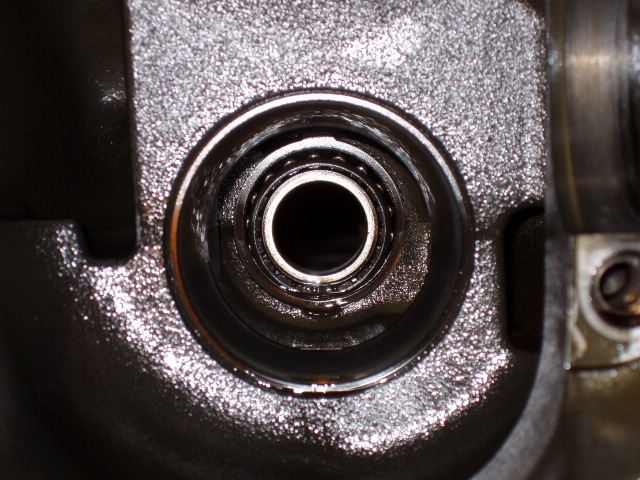 |
The new bearing races from the install kit need to be installed into the housing. Before doing so, be sure that there are no burrs in the race receptacles from when the old races were removed. Any burrs should be removed or pounded down with a punch. The races fit tightly and should be placed in a freezer for a few hours and then coated with gear lube before installation. The easiest way to install them is by pounding around the edge with a soft 1/2" rod and hammer. It'd be a good idea to have a Jeep buddy hold them so they don't pop out. Once they're pretty much installed, use the old bearing races as a drive and give them some really good whacks to make sure they're completely seated. |
| Fig 27: Inner and outer pinion bearing races and back of outer pinion bearing |
|
 |
Lubricate the setup bearings from behind the cages while periodically rolling them. Slip the inner pinion bearing on top of the shims on the pinion gear. Place the outer pinion bearing into the outer pinion bearing race in the housing. Fig. 27 shows how the old races and outer pinion bearing looked from inside the housing; this is also how the new races and setup outer bearing should look. Slip the pinion gear into the housing while holding the outer bearing from falling out. Slip the splined yoke and pinion nut washer onto the pinion gear. Being sure the convex side on the washer is facing out, finger tighten the pinion nut. |
 |
Screw three of the driveshaft bolts back into the yoke and place the Miller Holder over the them. The holder's handle should touch the ground on the left side of the Jeep. Tighten the pinion nut with an impact driver until bearing play is eliminated. The crush sleeve is being permanently crushed as the nut is tightened so don't overtighten. Once the play is eliminated, tighten the pinion nut to a minimum of 210 lb ft. with a 250 lb ft torque wrench. Remove the holder and measure the rotating torque as described below. |
 |
Spin the yoke back and forth a few times to loosen-up the bearings. Place the socket, correct drive adapters, and an inch pound torque wrench on pinion nut. Spin the wrench and record the sustained torque reading. A rotating torque of 10-30 lb in is required; the author aimed for 20 lb in. If the reading is out of the range, remove the inch pound wrench, reinstall the holder, and tighten the pinion nut another 5 lb ft with the 250 lb ft torque wrench. Repeat this step until the rotating torque is within the correct range. Don't overtighten or a new crush sleeve will be needed. |
